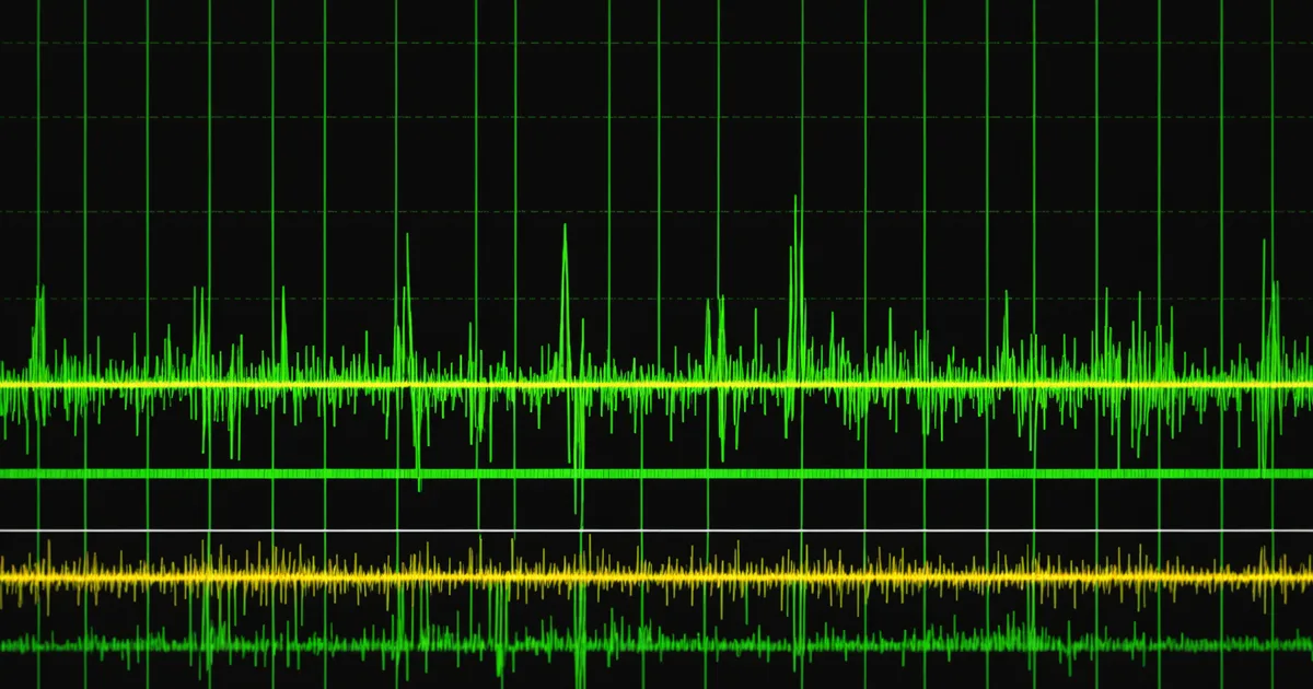
Upper-limb rehabilitation through functional electrical stimulation (FES) hinges on one practical question: how does the device know when the user wants to move? A timer-based protocol can trigger stimulation at regular intervals, but that is not closed-loop control. Genuine closed-loop FES requires a real-time intent signal, and for most upper-limb rehabilitation scenarios, residual surface EMG from the same or adjacent muscle groups is the most accessible and physiologically meaningful source of that signal.
This post walks through the signal chain from raw EMG at the electrode to a FES command dispatch. Each stage has its own tradeoffs and failure modes, and getting the integration right is where most embedded firmware teams spend the bulk of their time.
Why Residual EMG Is the Right Intent Source
Patients with incomplete spinal cord injuries, stroke motor deficits, or brachial plexus injuries often retain some residual voluntary EMG in the targeted muscle groups, even when that EMG is insufficient to drive useful movement on its own. The FES system uses that residual signal as a proportional intent indicator: higher voluntary activation level triggers higher stimulation intensity, which recruits additional motor units to complete the movement.
This is not the only approach. IMU-based gesture recognition, EEG-based motor imagery decoding, and force-sensing gloves have all been explored as intent sources. Each has a specific use case. We focus on surface EMG here because it has the shortest latency, requires no separate sensing modality, and provides a continuous proportional signal rather than a discrete class label. For upper-limb grasp and release tasks, that proportionality is valuable: you want graded force output, not a binary open/close command.
Stage 1: EMG Signal Conditioning
Raw surface EMG signals from a two-electrode differential pair are typically in the range of 50 microvolts to 5 millivolts peak-to-peak. The signal sits on top of a common-mode noise floor that can include 50/60 Hz power-line interference, motion artifact from cable movement, and stimulation artifact from the FES output itself when the same muscle group is being stimulated.
The instrumentation amplifier stage sets the common-mode rejection ratio (CMRR) baseline. For surface EMG in a rehab device, a CMRR above 80 dB at 60 Hz is a reasonable target. After instrumentation amplification, a bandpass filter that passes roughly 20 Hz to 500 Hz removes sub-20 Hz motion artifact and high-frequency noise above the useful EMG spectral content. For the FES closed-loop application specifically, you can push the lower cutoff higher, toward 30 Hz, because you are extracting an envelope rather than a spectral feature, and this helps suppress motion artifact from the limb movements FES itself is causing.
Stimulation artifact is a harder problem. When the FES electrodes are near the recording electrodes, the stimulation pulse couples into the recording chain and saturates the amplifier for tens to hundreds of microseconds. The practical fix is blanking: the firmware disables or clamps the amplifier input during the stimulation pulse window. Ruten's acquisition layer includes a configurable blanking window tied to the stimulation bus timing signals, which lets you blank precisely without discarding more signal than necessary.
Stage 2: Envelope Extraction
The raw bandpass-filtered EMG is a biphasic signal whose amplitude carries the intent information. To use it as a control signal, you need to extract a smooth envelope that tracks voluntary activation level without following individual motor unit firing patterns.
The standard approach is full-wave rectification followed by a low-pass filter. Rectification folds the negative half-waves to positive, and the low-pass filter smooths the result. The low-pass cutoff is a tradeoff: too low (below 3 Hz) and the envelope lags voluntary changes too much for real-time control; too high (above 10 Hz) and the envelope has too much residual ripple to threshold cleanly. A Butterworth filter at 5 Hz to 8 Hz with a 2nd or 3rd order implementation gives acceptable phase lag on a Cortex-M4 without requiring floating-point division per sample.
An alternative worth knowing is the root-mean-square (RMS) envelope computed over a sliding window. RMS has theoretical advantages in that it better tracks the power content of the signal, but in practice for threshold-based FES control the difference is marginal. RMS is more computationally intensive on a fixed-point DSP core. We default to rectify-then-lowpass in the Ruten middleware and let teams swap in an RMS path through the decoder configuration API if their specific use case calls for it.
Stage 3: Threshold Gating and Intent Classification
The smoothed envelope needs to cross a threshold before FES output begins. Threshold setting is where most groups run into problems in early integration. Set the threshold too low and voluntary tremor or baseline EMG noise triggers spurious stimulation. Set it too high and the device requires more voluntary effort than the patient can sustain, defeating the purpose of the assist.
Two threshold parameters matter: the onset threshold (where stimulation begins) and the offset threshold (where stimulation stops). Using a hysteresis band between these two values prevents rapid oscillation around the threshold boundary, which would cause uncomfortable on-off cycling of the stimulation output. A hysteresis of 10 to 20 percent of the onset threshold value is a reasonable starting point.
Adaptive threshold calibration is an active area in the research literature, and we are watching it closely. The intuition is straightforward: baseline voluntary EMG amplitude varies between sessions due to electrode placement, skin impedance, and fatigue, so a fixed threshold calibrated on day one drifts out of range over time. An online adaptation routine that tracks baseline EMG statistics during rest periods and adjusts thresholds accordingly can maintain consistent triggering without requiring per-session recalibration.
One boundary worth stating clearly: threshold gating is intent detection, not intent decoding. You are determining whether the user is attempting voluntary contraction above a level, not inferring what specific movement they intend. For simple grasp-release FES applications this is sufficient. For more complex multi-joint movements, you need an intent decoding stage layered on top, which is a different firmware problem.
Stage 4: Mapping Intent Level to FES Command Parameters
Once the threshold gate opens, the envelope amplitude above the onset threshold drives the FES command parameters. The primary parameters available are stimulation pulse amplitude (in milliamps), pulse width (in microseconds), and stimulation frequency (in pulses per second, PPS).
For proportional FES control, the most common approach is to modulate pulse width with a linear or slightly nonlinear mapping from the normalized envelope amplitude to the pulse width range. Amplitude modulation is also used, but pulse width modulation produces a more predictable force-recruitment curve on most peripheral motor nerves, and it is easier to keep within charge density safety limits when you are modulating pulse width rather than amplitude.
The mapping function matters. A linear map from EMG envelope to pulse width will feel stiff at low activation levels and saturate quickly. A slight expansion of the lower end (companding the signal upward for low-amplitude voluntary effort) makes the device more responsive to partial voluntary activation, which is exactly the population you are targeting in stroke rehabilitation. This companding curve is parameterizable in Ruten's stimulation command bus configuration.
Stimulation frequency is typically held constant in simple closed-loop EMG-FES systems, at around 20 to 40 PPS, because the motor neuron recruitment relationship with frequency is less predictable than the pulse-width relationship. Some research groups modulate frequency as a second degree of freedom for finer force control, but this adds firmware complexity and the perceptual comfort range for frequency modulation is narrower than for pulse width.
Where Middleware Changes the Integration Equation
The signal chain described above, from differential EMG input through blanking, envelope extraction, threshold gating, and FES command dispatch, involves coordination across the acquisition layer, the decoder configuration, the stimulation command bus, and the timing synchronization between stimulation output and recording blanking windows. Building this from scratch on a new hardware platform requires writing and testing each layer in isolation before the end-to-end timing relationships can even be verified.
The practical advantage of middleware like Ruten is that the cross-layer timing contracts are pre-defined. The acquisition layer exports blanking trigger timestamps. The decoder layer consumes those timestamps and gates processing accordingly. The stimulation bus accepts command events with explicit timing references. When you bring up a new EMG electrode array or a new FES stimulator hardware, you implement the device adapter and the cross-layer behavior is inherited. The integration work shrinks from building a signal chain to validating a hardware adapter.
We saw this concretely when integrating a second stimulator hardware variant alongside an existing amplifier setup. The EMG signal conditioning parameters and the FES command mapping logic did not change. Only the stimulator-side device adapter needed to be written and validated. That is the value proposition for a team of firmware engineers trying to move from a working prototype to a device that runs on multiple hardware configurations without re-deriving the closed-loop timing logic each time.