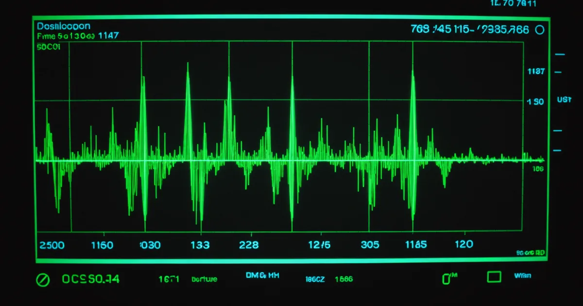
If you have built a closed-loop EEG system and you have tried to use the same electrode array for both recording and stimulation, you already know the artifact problem. The stimulation pulse saturates the amplifier. The amplifier spends the next several milliseconds recovering. During that recovery window, the signal you are trying to decode is invisible. For some closed-loop applications, that gap is acceptable. For high-frequency, short-interval stimulation protocols, it is not.
At Ruten, the stimulation artifact problem is central to the decoder layer design, not an edge case we handle after the fact. This post covers the strategies we have built into the middleware for rejection, blanking, and post-artifact recovery, and explains where each approach applies and where it fails.
Why the Artifact Is Hard to Separate
A stimulation artifact in an EEG recording looks like a large-amplitude transient: typically two to three orders of magnitude larger than the neural signal of interest. The artifact has a fast onset corresponding to the stimulation pulse edge and a slower exponential decay corresponding to the electrode-tissue interface capacitance discharging. The decay tail can extend for 10 to 50 milliseconds depending on pulse energy, electrode impedance, and amplifier design.
The core difficulty is that the artifact occupies the same frequency bands as the neural signals you care about. A 30 Hz FES burst will produce artifact content at 30 Hz and harmonics, overlapping directly with the gamma band that many motor imagery decoders use. Bandpass filtering does not help. The artifact is spectrally broadband because of the sharp transient edges, and the exponential decay tail adds low-frequency content that can corrupt LFP power estimates for hundreds of milliseconds after each pulse.
The second difficulty is that the artifact shape is not constant. It changes with electrode impedance drift, subject movement, and sweat accumulation under gel electrodes. A fixed template subtraction that worked in the morning calibration session may produce residuals that are larger than the neural signal by the afternoon session. Any rejection strategy that assumes a static artifact template will degrade over a recording session.
Strategy 1: Blanking
The most reliable artifact rejection strategy is also the most aggressive: gate the decoder input off during and immediately after each stimulation event. In the Ruten middleware, the stimulation command bus sends a blanking signal to the decoder layer every time a pulse is dispatched. The decoder freezes its output for a configurable window, defaulting to the pulse duration plus a recovery margin.
Blanking is the right choice when the inter-stimulus interval is long relative to the artifact decay time. For a 30 Hz burst protocol where each burst lasts 10 cycles at 100 Hz, the inter-burst interval is around 33 ms. A 15 ms blanking window per burst keeps the decoder blind for less than half the inter-burst period. The downstream application can interpolate or hold the last valid decode state across the blank.
Blanking fails when stimulation is continuous or nearly continuous. If the inter-stimulus interval is shorter than the blanking window, the decoder never sees valid data. That situation is uncommon in FES rehabilitation protocols, but it can arise in spinal cord stimulation paradigms with burst-mode patterns where stimulation is nearly continuous at frequencies above 100 Hz.
What the Blanking Window Should Cover
The most common mistake we have seen in hand-rolled blanking implementations is setting the window too short. The blanking window is not just the pulse duration. It needs to cover: the pulse itself, the amplifier saturation period, and the electrode-tissue interface discharge tail. For a typical gel electrode on scalp EEG with a mid-range amplifier, that tail can extend 8 to 12 milliseconds after a 300 microsecond biphasic pulse at 6 mA.
In the Ruten decoder, the blanking window duration is set per-channel and configurable at runtime. The default is calculated from the pulse parameters passed through the command bus: pulse width multiplied by 1.5 for the amplifier recovery margin, plus a constant 8 ms for the electrode tail. That heuristic is not correct for every amplifier and electrode combination, but it errs on the side of throwing away more signal rather than less during the artifact window.
Strategy 2: Template Subtraction
When blanking is not viable because inter-stimulus intervals are too short, template subtraction offers an alternative. The idea is to estimate the expected artifact waveform and subtract it from the recorded signal, leaving (ideally) the neural component.
The template is estimated during an initial calibration period by averaging many artifact trials aligned on stimulation onset. Averaging reduces the contribution of the neural signal (which is uncorrelated with stimulation timing) and leaves the stereotyped artifact shape. The cleaned template is then stored and subtracted in real time on each new stimulation cycle.
We implemented an adaptive variant of template subtraction in the Ruten decoder where the template is updated incrementally using an exponential forgetting factor. Each new artifact trial updates the stored template by a small fraction, typically 0.05 to 0.10, blending the historical average with the current observation. This allows the template to track slow drift without requiring a full recalibration when electrode impedance changes.
Template subtraction works well when the artifact is consistent within a session and the neural-signal-to-artifact ratio in the subtraction residual is better than about 0.1. When artifact variability is high, the residuals after subtraction can still saturate the decoder's dynamic range, and the cleaned signal looks worse than blanking would have produced.
Strategy 3: Hardware-Level Mitigation and Software Interplay
Neither blanking nor template subtraction eliminates the root cause of the artifact problem, which is that the recording amplifier sees the stimulation voltage. Some hardware platforms include artifact-rejection circuitry at the amplifier frontend: sample-and-hold circuits that freeze the amplifier input during the pulse, or switched-capacitor designs that isolate the recording path during stimulation. When the hardware supports it, combining hardware-level artifact gating with software blanking in the decoder produces cleaner residuals than software alone.
The Ruten adapter interface includes an optional hook for hardware artifact gating: on_stim_pre() and on_stim_post() callbacks that the stimulation command bus calls immediately before and after each pulse dispatch. An adapter for a hardware platform with analog switching can use those callbacks to toggle the hardware gate. An adapter for a platform without that capability simply leaves the hooks as no-ops. The decoder blanking window still activates regardless, since the blanking trigger is generated by the command bus independently of whether hardware gating is available.
What We Do Not Support Yet
We should be direct about the current limitations. The decoder does not implement independent component analysis (ICA) or any other blind source separation approach for artifact removal. ICA-based artifact rejection is well-established in the EEG literature for offline processing, and there are real-time variants designed for closed-loop systems. We have prototyped a reduced-basis ICA approach on host-class hardware and the computational cost on a 128-channel array is within reach on a modern cortex-A processor. The challenge is that ICA requires the artifact-free mixing matrix to be estimated and held stable. In a closed-loop session where stimulation parameters change adaptively, reestimating the mixing matrix frequently enough to track the changes while maintaining a stable decode is a problem we have not solved to our satisfaction.
We are not claiming that ICA-based rejection is the wrong direction. We are saying that the current state of our implementation is blanking for sparse stimulation and adaptive template subtraction for denser protocols. Those two strategies cover the majority of FES and cortical stimulation protocols we have encountered in the neuro-rehabilitation device space, and they are deterministic enough that device makers can reason about the decoder's behavior under worst-case artifact conditions.
Practical Guidance for System Design
If you are designing a closed-loop system that uses the same electrode array for recording and stimulation, the decision between blanking and template subtraction should be driven by your stimulation duty cycle. Compute the fraction of time the decoder would be blanked under your intended protocol. If it is below 30 percent, blanking is simpler and more predictable. If your protocol demands a higher duty cycle, explore template subtraction with the understanding that you will need a calibration procedure before each session and a monitoring step to detect when the template has drifted enough to invalidate the subtraction.
The worst outcome is applying template subtraction in a system with high artifact variability and assuming the cleaned signal is neural. The decoder may produce outputs that look reasonable but contain structured artifact residuals that correlate with stimulation parameters rather than neural activity. Validating the cleaned signal against a period with stimulation switched off is a minimum sanity check before trusting the decode quality in any protocol that uses adaptive template subtraction.